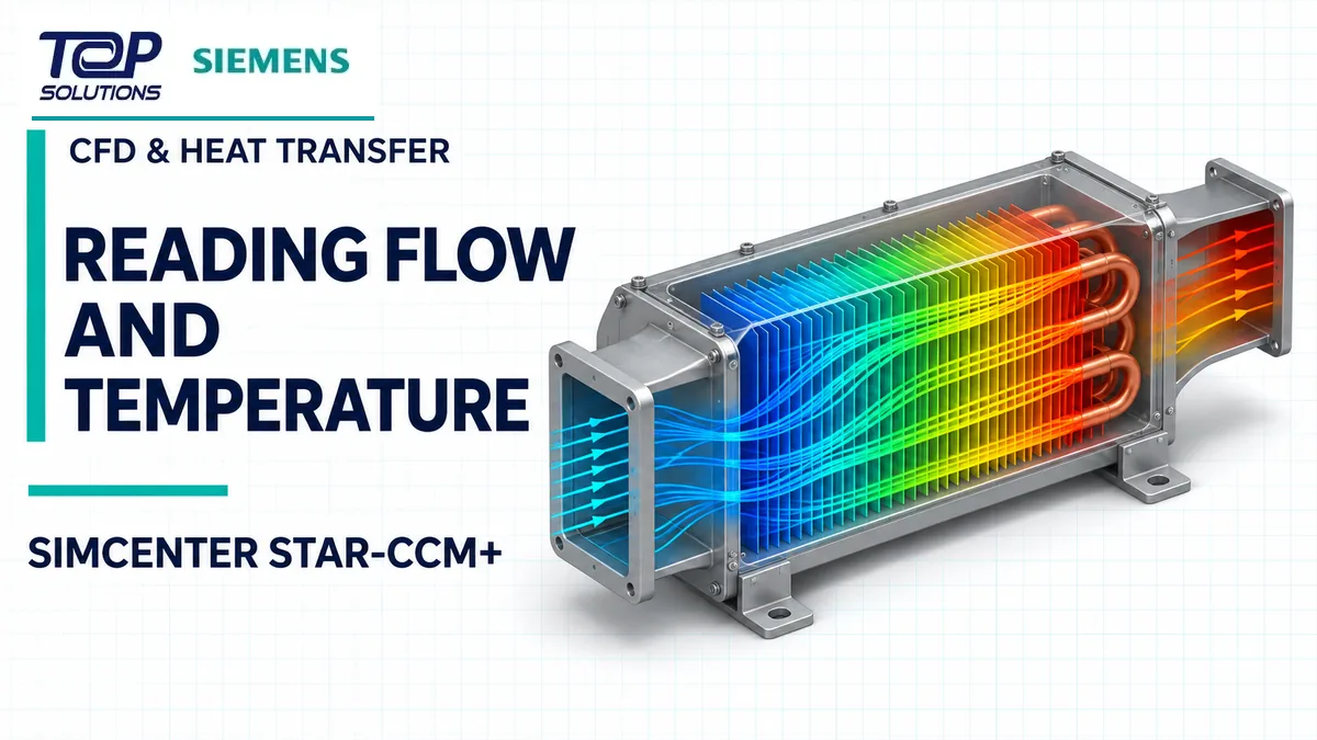
A heat exchanger or finned cooling assembly inside an air duct must be assessed for airflow, temperature and pressure loss together. This illustrative example lays out a workflow in Simcenter STAR-CCM+ . Boundary values are assumptions. No solver result is presented; the article explains what to inspect once a model has been run.
1. Build fluid and solid regions
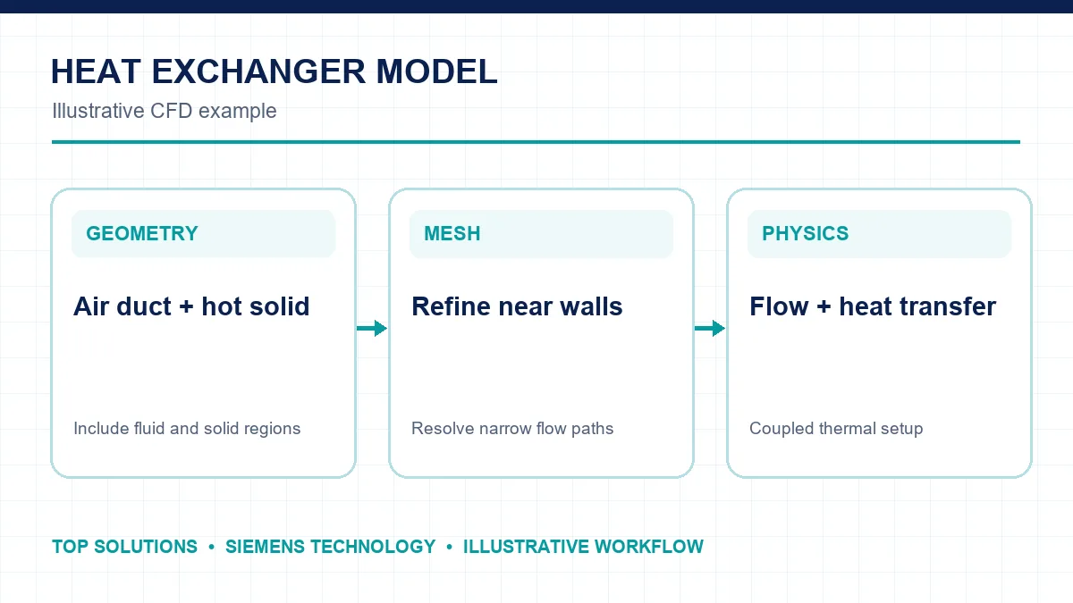
The model contains an air duct, fins and a heat-generating solid. Separate the air and solid regions, assign materials and define thermal contact at their interface. Refine the mesh in narrow fin gaps, near walls and where steep temperature gradients are expected. Check mesh quality before solving; an attractive geometry alone does not establish result reliability.
2. Define boundary conditions and comparison goals
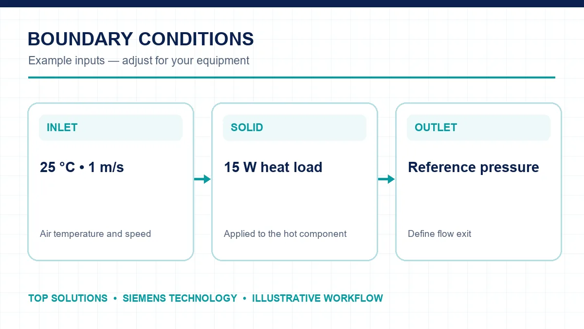
For this example, assume 25 °C inlet air at 1 m/s, a 15 W solid heat load and a reference-pressure outlet. Record material properties, flow direction, steady or transient assumptions and any environmental heat loss. When comparing two fin designs, hold the heat load and inlet conditions constant.
3. Read flow and thermal fields
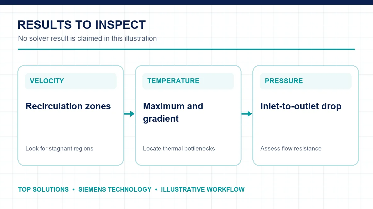
Once the solution has converged, inspect streamlines or velocity sections for stagnant and uneven-flow regions. Review maximum solid temperature, outlet air temperature and gradients at thermal interfaces. Calculate inlet-to-outlet pressure drop to see whether stronger cooling comes with excessive flow resistance.
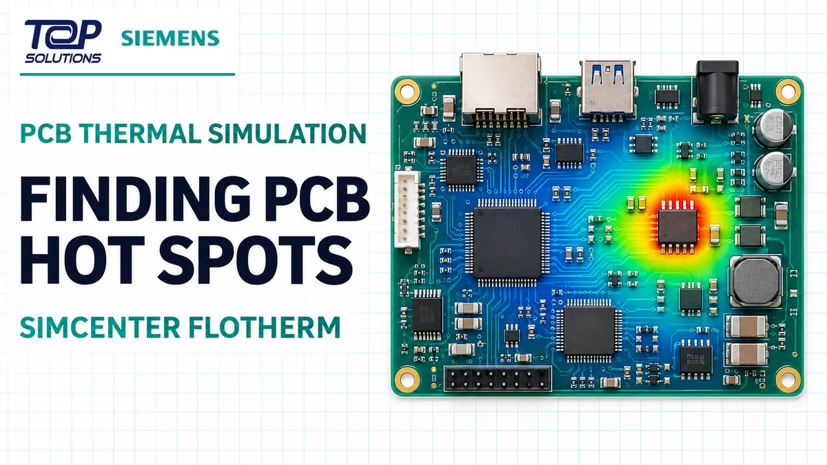
Do not decide from a contour image alone. Check energy balance, convergence history and mesh sensitivity. If peak temperature or pressure drop changes substantially after refinement, continue the study before selecting a design.
Choosing a CFD tool
STAR-CCM+ supports complex fluid, thermal and multiphysics studies. See the broader Siemens Simcenter CFD solutions page for context.
Technical source: Siemens – Simcenter STAR-CCM+ software.